Subdivision Design
Step Action
1. Start a New Job
2. Define Points
3. Form Lots
4. Adjust Lot Areas
The Program is a “general purpose” calculation and drawing package for surveying work.
It can accept data in a variety of forms including that from data recorders, process this data,
produce drawings and export the data in a variety of export formats.
All processing is carried in memory and the results saved to disk at the end of a processing session.
Start a new Job
To start a new job select File then New.
This will set up a new job ready for work. If the aim of the session is simply to make a
few calculations and print the results, then the user can proceed with the work and exit.
When you exit, the program will ask whether you wish to save the data and if “yes” is
selected it will allow you to name the file and store it using the windows file management procedures.
If the job is to be a ongoing project, it is better to set up the final data file at the
start by selecting File again and then Save as to record the new file name.
This exercise is to compute a new twenty six lot subdivision and prepare the plan for the
Land Titles office.
The general layout has been sketched out and councils requirements are that lots are to be
in excess of 700 metres square in area, the minimum depth to be 20 metres, and minimum
frontage to be 12 metres.
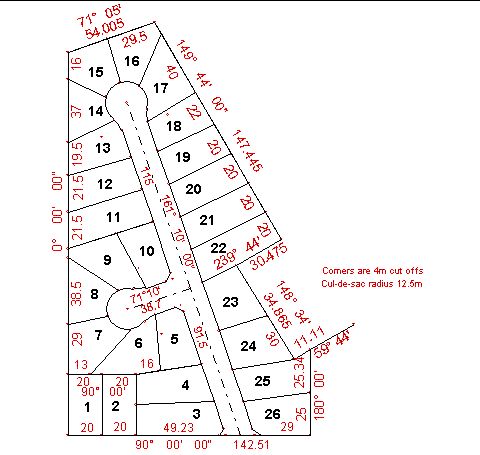
The surround for the block and the road centre lines are shown in Fig 1, start at the bottom
left corner and enter the bearings and distances for the surround an check the misclose.
Define Points
Use Points/Geom/Fixed point to enter point 1 as 1000E, 1000N.
The actual value adopted is not important as the job can be moved to any co-ordinate system at
a later date.
Then use Points/Geom/Bearing, Distance to enter the lines in sequence around the block.
The last point (number 10) should coincide with the first unless there is a misclose.
Use F3 (or Show/Bearing, Distance) to display the misclose, which in this case is less
than a centimetre so we can either disregard it or distribute it in the surround.
For the remainder of the work is more convenient to convenient to use the Points Toolbar
which is selected with View/Points Toolbar. The toolbar can be moved around and parked
out of the way of the drawing.
Enter the road centre lines and check the distances square off the boundaries for the centre
points of the cul-de-sac turning circles using F4 or Show/Square Offset.
Point 12 is 35.206 off the line 1 to 2, point 11 is 34.701 off the line 1 to 2, 39.401 off the
line 2 to 3 and 38.001 off the line 3 to 4.
As the radius of the cul-de-sac turning circle is 12.5 metres, all centres are OK.
Now enter all the points along the straight lines using the Bearing Distance option.
Note that if successive distances are the same you can use the Repeat button to create
the next point.
Once all of the points for a lot have been generated, the lot record can be built with the
Strings function.
Form Lots
Select Edit/Strings/Insert string. Type in the lot number in the
Name box , toggle the Type box to select “Lot” and select the Layer.
The normal default is the “Strings” layer, but on large projects, you may wish to subdivide the
strings to make a layer for each proposed Deposited Plan.
If you wish to set up a new layer use Edit/Layers and hit the “New Layer” button.
The colour, style and width for lines can be set by toggling the respective boxes, but in most
cases the default values are appropriate.
Once the attributes for the lot are correct you can proceed to select the lines to define the
boundaries. Start at the street frontage and proceed around the block in a clockwise direction
selecting the start and end of each line with the mouse. The cursor will change from an arrow
to a target symbol when it is close enough to select a point and the lines are drawn on the
screen to provide a visual check on your work.
Normally the program automatically jumps from the Pt A box to the Pt B box,
but for curved lines, after selecting the start point select the Centre box, click on the
centre point and then the end point.
When the lot is completed (that is the last Pt B is the same as the first Pt A)
click the “End String” button and proceed to the next lot. The attributes will remain the same
as the previous lot so that it is only necessary to enter the lot number in the “Name” field
before selecting the lines.
The lot number and area will be displayed if these parameters are active in the display settings.
The normal default is for them to be active, but if they are not displayed select
View/Display settings and tick the respective boxes.
Adjust Lot Areas
Some people may to check the area of each lot as it is created.
If it is not satisfactory some of the corners can be moved to correct the problem. Note that
the strings definition describes each string (and a lot is a “string”) in terms of the point
numbers around the boundary. If you change the coordinates of the points, the physical location
of the boundary changes, but the string definition remains the same.
Rather than adjust each lot as it is created, I prefer to create all the lots and then look at
the subdivision as a whole before adjusting any boundaries.
The initial design for the subdivision is shown in figure 1 and the areas of lots five to
nineteen are as follows:
| Lot |
Area (SqMetres) |
Lot |
Area (SqMetres) |
| 5 |
676 sqm |
12 |
854 sqm |
| 6 |
801 sqm |
13 |
746 sqm |
| 7 |
803 sqm |
14 |
613 sqm |
| 8 |
683 sqm |
15 |
701 sqm |
| 9 |
861 sqm |
16 |
706 sqm |
| 10 |
692 sqm |
17 |
833 sqm |
| 11 |
933 sqm |
18 |
697 sqm |
| |
|
19 |
779 sqm |
Lots 5, 8, 10, 14 and 18 are short in area and need to have their boundaries adjusted. Lot 5
requires an additional 24 square metres and this can be taken from lot 6 to the west by moving the south west corner (point 51). Use F3 to check the length of the western boundary (point 51 to point 49 is 33.155 metres). As the sliver to be added is a triangle, the base will be roughly twice the area divided by the line length so 48/33 is approximately 1.5 metres.
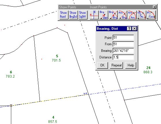
Select Points/Geom/Bearing Distance and in the dialogue box, Point =51,
From =51, Bearing click points 51 and then 41 to define the direction to move
along that line, Distance = 1.5
The areas for lots 8,9 and 10 can be adjusted in a similar manner by moving point 19 along
the line 18 to 20 and point 61 along the line 58 to 20.
To correct the area of lot 14 it will be necessary to change the boundary between lots 13
and 14 so that arc from 66 to 64 is part of lot 14. As the frontages of these lots are curves,
the simplest way is to delete the old string definitions and re-enter them for the new boundaries.
To delete a string, select it by clicking on one of the straight lines (for lot 14, the
back line from 23 to 24 is the easiest to use – if you use a side line you may get the adjacent lot).
The corner points of the string will be blocked to indicate that the string has been select.
Once the string has been selected, the delete key will remove the string.
After re-entering lots 13 and 14 there will still be a shortage in lot 14 and this can be
corrected by moving points 22 and 60. Lot 18 also requires a small adjustment and this
can be by moving the back corner (point 30) 0.2 metres towards point 31.
The subdivision design is now complete.